
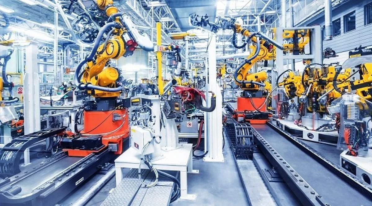
Learn how to install and wire Yaskawa AC Adjustable Frequency Drives, including power, motor, control wiring, grounding, shielding, commissioning, and troubleshooting.
Yaskawa AFD Installation Guide: Proper Wiring, Power Connections, Grounding, Control Setup, I/O Configuration, and Safety Commissioning
Installing a Yaskawa AC Adjustable Frequency Drive (AFD) correctly is more than connecting three incoming power wires and three motor wires. A reliable installation requires correct drive selection, physical mounting, branch-circuit protection, input and motor wiring, control-circuit separation, grounding, shielding, parameter configuration, and a controlled commissioning process. A wiring mistake at any one of these points can produce nuisance faults, motor damage, electrical noise, overheating, or an unsafe installation.
Yaskawa AFD installation begins with correctly identifying the drive model, voltage class, motor requirements, and applicable installation manual before connecting power. Incoming three-phase power normally lands on the drive input terminals, while the motor connects to the dedicated drive output terminals; control wiring and grounding must be installed according to the specific Yaskawa drive family and application. Proper conductor sizing, grounding, shielding, terminal torque, separation of power and control wiring, and systematic commissioning are essential for dependable motor control and long-term drive performance.
Safety note: AC drives contain hazardous voltages and energy stored in DC-link capacitors even after incoming power is disconnected. Installation, wiring, testing, and servicing should be performed by qualified personnel using the applicable electrical code, lockout/tagout procedures, and the exact Yaskawa manual for the drive being installed. Never rely on this guide as a substitute for the manufacturer’s installation documentation.
Understanding the Yaskawa AFD Power Flow Before Wiring
A Yaskawa AC drive sits between the electrical supply and the motor. Its job is to convert fixed-frequency AC input power into controlled motor power with adjustable frequency, voltage, and—in appropriate control modes—torque.
The basic power path is straightforward:
AC power source → branch protection/disconnect → Yaskawa AFD → motor
Internally, the drive rectifies incoming AC power into DC, stores and filters that energy on the DC bus, and then uses an inverter stage to synthesize the controlled AC waveform supplied to the motor.
This is why an AFD should not be treated like a conventional motor starter. The motor does not receive the utility waveform directly. The drive generates the motor-side output.
That distinction becomes particularly important when wiring the main circuit. On many Yaskawa drives, including the GA800, the incoming supply terminals are identified as R/L1, S/L2, and T/L3, while the motor output terminals are U/T1, V/T2, and W/T3. Yaskawa’s current GA800 installation documentation explicitly identifies R/L1, S/L2, and T/L3 as the main circuit power input and U/T1, V/T2, and W/T3 as drive output terminals for connection to the motor.
The exact terminal arrangement is not universal across every Yaskawa product family. A V1000, A1000, GA500, GA700, GA800, Z1000, or specialized drive can have different physical layouts and control terminals.
For that reason, the first rule of installation is simple:
Identify the exact drive model before connecting a conductor.
Automation Pioneer maintains a broad selection of industrial variable-frequency drives and Yaskawa equipment, including Yaskawa AC drives. Browse Variable Frequency Drives (VFDs) at Automation Pioneer
What to verify before opening the drive
Before wiring begins, verify the drive nameplate and installation documentation for:
Drive model and suffix
Input voltage class
Input phase requirements
Motor voltage
Motor full-load current
Drive horsepower or kW rating
Normal-duty and heavy-duty ratings where applicable
Enclosure/environmental rating
Short-circuit current rating requirements
Required branch protection
Wire range
Terminal tightening torque
Grounding requirements
Control terminal configuration
EMC/filter configuration
Braking resistor requirements
Communication or feedback options
Required clearances and ventilation
Do not select wire size based solely on the motor horsepower printed on the motor. The drive manual, applicable electrical code, conductor temperature rating, installation method, ambient temperature, grouping, and other derating factors must all be considered.
Yaskawa AFD Installation: Mounting and Panel Preparation
Correct wiring starts with correct mechanical installation.
A drive that is mounted in a hot, contaminated, wet, or poorly ventilated enclosure can experience problems even when every terminal is wired correctly.
Mount the drive in the orientation specified by Yaskawa and maintain the manufacturer’s required clearances around the enclosure and heat sink. Drives generate heat during normal operation, and the enclosure must provide a suitable thermal environment.
Avoid installing a drive immediately above equipment that produces excessive heat. Likewise, do not place heat-sensitive components directly beneath the drive’s hot-air exhaust path.
Consider the enclosure environment
Industrial installations commonly expose drives to:
Dust
Oil mist
Moisture
Corrosive chemicals
High ambient temperatures
Vibration
Electrical noise
Conductive contamination
The correct enclosure and environmental rating depend on the application.
A clean indoor machine panel is a very different environment from a wastewater plant, steel mill, food-processing facility, or outdoor pump station.
Provide the correct disconnecting means
The drive installation should include appropriate means for disconnecting and isolating the incoming power in accordance with the applicable electrical requirements.
Branch-circuit protection must also be selected according to the drive manufacturer’s requirements and the governing electrical code.
Do not simply install an oversized breaker because the motor is large. Protection must coordinate with the drive, conductors, and installation requirements.
Keep the installation serviceable
A good panel design leaves enough physical access to inspect terminals, replace components, connect a keypad, troubleshoot faults, and perform maintenance.
Crowding a drive against wire duct or adjacent heat-producing equipment makes future maintenance harder and can compromise cooling.
Wiring the Yaskawa AFD Incoming Power Terminals
Once the drive is mechanically installed and the branch circuit is isolated, the next task is the incoming power connection.
For a typical three-phase Yaskawa drive, the power supply connects to:
R/L1 → Line 1
S/L2 → Line 2
T/L3 → Line 3
The exact terminal names and arrangement must be verified against the applicable model manual.
Yaskawa’s GA800 documentation identifies R/L1, S/L2, and T/L3 as the commercial power input terminals. It separately identifies U/T1, V/T2, and W/T3 as motor output terminals.
That separation is fundamental.
Never connect incoming power to the motor terminals
Do not connect utility power to U/T1, V/T2, or W/T3.
Yaskawa specifically warns against connecting power supply wiring to the drive output terminals. Doing so can cause catastrophic drive failure and create a serious electrical hazard.
The practical rule is:
Line power goes to the input side. The motor goes to the output side.
Do not assume terminal locations from another Yaskawa drive. Even closely related products can have different physical terminal arrangements.
Input conductor considerations
Select the incoming conductors based on:
Drive input current
Applicable electrical code
Conductor insulation rating
Installation temperature
Raceway or cable installation method
Ambient temperature
Number of current-carrying conductors
Terminal limitations
Manufacturer requirements
The conductor must physically fit the drive terminal and be secured using the specified termination method.
For larger GA800 frame sizes, Yaskawa documentation provides specific wire ranges and terminal tightening torques. For example, one GA800 frame drawing specifies separate ranges and torque values for input, output, DC bus, and grounding terminals. Those values are not universal and demonstrate why installers should use the exact documentation for the particular frame.
Tightening torque matters
Loose terminals create resistance.
Resistance creates heat.
Heat creates additional resistance and can eventually damage the terminal, conductor, insulation, or drive.
Therefore, terminal torque is not a minor installation detail. Use a calibrated torque tool and the exact torque specified for the terminal.
Do not substitute a torque value from another Yaskawa model.
Wiring the Yaskawa AFD Motor Output
The motor-side connection is normally made from:
U/T1 → Motor T1/U
V/T2 → Motor T2/V
W/T3 → Motor T3/W
Again, terminal labels vary by product, but the principle is the same: the motor must be connected to the drive’s designated output terminals.
The motor cable should be selected for the electrical and environmental characteristics of a VFD installation rather than simply treating it like an ordinary across-the-line motor connection.
Do not switch the motor with a contactor while the drive is producing output
A common mistake in retrofit installations is placing a contactor between the drive and motor and opening or closing it during normal drive operation.
That arrangement can interrupt the drive output under load and create severe electrical stress.
If a motor disconnect or bypass arrangement is required, it must be engineered specifically for the drive system and controlled so the drive is not exposed to an improper switching condition.
Motor phase sequence
If the motor rotates in the wrong direction, do not change the incoming utility phase sequence as the first troubleshooting step.
The motor direction is determined by the drive’s output phase relationship.
With power safely isolated and following the manufacturer’s procedure, interchange two motor output conductors if the specific application and drive documentation permit that approach.
Alternatively, the drive may provide a programmed direction command or motor rotation setting.
Motor cable length matters
Long motor cables can increase reflected-wave effects, common-mode current, electromagnetic interference, and insulation stress.
The permissible motor cable length depends on the drive, motor, carrier frequency, cable construction, installation method, and whether output filtering is used.
For long motor runs, evaluate whether the installation requires:
Output reactors
dv/dt filters
Sine-wave filters
Shielded VFD cable
Reduced carrier frequency
Motor insulation suitability
Bearing-current mitigation
Do not assume that a motor cable that worked perfectly with a short 20-foot run will behave the same way on a 300-foot run.
Control Wiring: Digital Inputs, Analog Signals and Communication
Power wiring gets most of the attention, but poor control wiring is one of the most common causes of difficult-to-diagnose drive problems.
A Yaskawa AFD can receive commands from a keypad, digital inputs, analog signals, a PLC, a network, or a combination of these depending on the model and configuration.
The control system may include:
Run/stop commands
Forward/reverse commands
External fault inputs
Multi-speed commands
Analog speed reference
Analog feedback
Digital status outputs
Fault relay contacts
Encoder feedback
Ethernet communications
Modbus communications
Other fieldbus options
The exact terminal design must be taken from the drive manual.
Separate control wiring from power wiring
Do not bundle low-level analog or communication conductors tightly alongside high-current motor conductors.
VFD output wiring produces high-frequency electrical noise because the inverter switches power devices rapidly to synthesize the motor waveform.
Poor routing can introduce noise into:
0–10 V signals
4–20 mA signals
Encoder signals
PLC inputs
Communication networks
Instrumentation
Safety circuits
Use appropriate separation, shielding, routing, and grounding practices.
Yaskawa documentation for communication installations specifically recommends shielded, twisted-pair wiring rather than unshielded control wiring and provides grounding guidance for the cable shield.
Analog speed reference
A common industrial arrangement uses a PLC or controller to send a speed reference to the drive.
For example, a PLC may command:
0–10 V
4–20 mA
Network-based speed reference
The drive then converts that command into a frequency or speed reference according to its configuration.
The signal type must match the programmed input configuration.
Do not connect a 4–20 mA source to an input configured or wired for a voltage signal.
Digital run command
A digital input can be used for commands such as:
Run forward
Run reverse
External fault
Jog
Multi-step speed
Reset
The actual function assigned to each input depends on the drive parameters.
That means wiring alone does not define the control system.
The physical input and the parameter assignment must agree.
PLC integration
Modern Yaskawa drives can be integrated into larger automation systems where the PLC controls speed and operating state while the drive provides status, current, frequency, alarms, and diagnostic information.
Automation Pioneer also documents the broader role of VFDs in industrial automation, including PLC, SCADA, and sensor integration. Read Automation Pioneer’s VFD fundamentals guide
For a networked installation, determine exactly where the command authority resides.
A drive should not simultaneously receive conflicting run commands from the keypad, hardwired inputs, and PLC network unless the control architecture intentionally supports that arrangement.
Yaskawa AFD Grounding: The Part You Cannot Treat as Optional
Grounding is not an accessory to the drive installation.
It is part of the electrical system.
Yaskawa’s GA800 documentation identifies dedicated grounding terminals and specifies grounding requirements based on voltage class. For example, the current GA800 installation manual identifies different grounding resistance requirements for 200 V and 400 V classes.
The exact grounding requirements for your installation must come from the applicable drive manual and electrical code.
Ground the drive chassis
Connect the protective grounding conductor to the drive’s designated grounding terminal.
Do not improvise a grounding point on the drive chassis.
Do not use a random mounting screw unless the manufacturer’s documentation specifically identifies it as a grounding point.
Ground the motor
The motor frame also requires proper protective grounding.
The grounding conductor should run with the motor circuit conductors and terminate at the appropriate grounding points.
This creates a low-impedance fault-current path and helps control high-frequency common-mode currents generated by the drive.
Do not ground power terminals
Yaskawa specifically warns against connecting the main circuit or DC bus terminals to the ground terminal. Those terminals are not grounding points.
This sounds obvious, but wiring mistakes often occur when technicians work from memory rather than from the exact terminal diagram.
Shield grounding
Where shielded motor or control cable is required, the shield termination method matters.
High-frequency noise does not behave like ordinary 60 Hz current. A long, thin grounding lead can have significant impedance at high frequencies.
For that reason, VFD shield termination should follow the manufacturer’s EMC recommendations and the application standard.
Separating Power, Motor and Control Wiring
A clean panel has a deliberate wiring architecture.
A practical arrangement separates:
Power input wiring
from
Drive-to-motor wiring
from
Control and instrumentation wiring
from
Communication wiring
This separation reduces electromagnetic interference and makes troubleshooting easier.
Why motor cables are especially important
The output waveform from a PWM inverter contains high-frequency switching components.
Those components can couple into nearby circuits through:
Capacitive coupling
Inductive coupling
Common impedance
Radiation
A control cable routed parallel to a motor cable for a long distance is therefore more likely to experience interference than a control cable routed separately.
Do not wait until the system develops unstable analog readings to correct poor cable routing.
Design the routing correctly during installation.
Commissioning a Yaskawa AFD After Wiring
Once wiring is complete, commissioning should be systematic.
Do not immediately press RUN and hope the motor behaves.
Start with a de-energized inspection.
Step 1: Verify the power circuit
Confirm:
Correct input terminals
Correct voltage
Correct phase configuration
Correct branch protection
Correct conductor size
Correct terminal torque
No exposed conductor strands
No accidental shorts
Proper grounding
Step 2: Verify the motor circuit
Confirm:
Motor is connected to U/T1, V/T2, W/T3 or the equivalent designated output terminals
Motor nameplate voltage matches the drive configuration
Motor full-load current is correctly entered
Motor frequency is correct
Motor base speed is correct
Motor wiring configuration is correct
Motor ground is connected
Step 3: Verify control wiring
Check:
Run command
Stop command
Direction command
Speed reference
External fault circuits
Interlocks
PLC signals
Communication wiring
Emergency-stop architecture
Safety circuits should be engineered according to the applicable machine-safety requirements and should not be improvised through an ordinary drive run command.
Step 4: Program the motor data
Motor nameplate information is critical.
Depending on the Yaskawa drive and selected control mode, parameters can include:
Motor voltage
Motor current
Motor frequency
Motor speed
Motor power
Motor poles
Acceleration time
Deceleration time
Maximum frequency
Minimum frequency
Control method
If the drive supports an automatic motor-tuning procedure, use the procedure appropriate for the motor and application.
Step 5: Perform a controlled test run
Start at a conservative speed.
Verify:
Rotation direction
Motor current
Frequency
Acceleration
Deceleration
Mechanical response
Vibration
Noise
Process response
Do not immediately operate a conveyor, pump, fan, or machine at maximum speed.
First establish that the electrical system and motor respond correctly.
Common Yaskawa AFD Installation and Wiring Mistakes
Connecting line power to drive output terminals
This is one of the most serious wiring errors.
The incoming supply belongs on the input terminals. The motor belongs on the output terminals.
Yaskawa explicitly warns against applying power to U/T1, V/T2, and W/T3.
Using the wrong wire size
A conductor that physically fits a terminal is not automatically electrically appropriate.
Wire sizing must account for ampacity, installation conditions, code requirements, and manufacturer specifications.
Guessing terminal torque
Terminal torque is part of the installation specification.
Too loose can cause heating.
Too tight can damage the terminal or conductor.
Use the specified value.
Poor grounding
A drive can appear to work with inadequate grounding and still create serious EMC, safety, and reliability problems.
Ground the drive, motor, and other required equipment according to the manufacturer’s instructions and applicable code.
Running analog signals beside motor cables
This is a classic source of unstable readings and communication problems.
Separate the wiring physically and use the appropriate shielded cable.
Ignoring motor cable length
Long cable runs can change the electrical behavior of the drive/motor system.
Evaluate filters, cable type, carrier frequency, motor insulation, and manufacturer limitations where required.
Leaving conflicting command sources enabled
A technician may test the drive from the keypad while the PLC is simultaneously configured as the run-command source.
That can create confusing behavior.
Establish one deliberate command architecture before commissioning.
Troubleshooting a Yaskawa AFD Installation
When a newly installed drive does not operate correctly, troubleshoot in layers rather than changing random parameters.
Start with the power system.
Drive will not power up
Check:
Incoming voltage
Disconnect status
Branch protection
Input terminals
Phase availability
Drive status indicators
Control power requirements
Wiring and terminal torque
Drive powers up but motor does not run
Check:
Run-command source
Digital input status
Frequency reference source
Minimum-frequency setting
External fault input
Interlocks
PLC command
Stop command
Drive alarm/fault status
Motor runs but rotates incorrectly
Check the commanded direction and the motor output phase relationship according to the drive’s installation procedure.
Drive trips during acceleration
Possible causes include:
Excessive acceleration demand
Mechanical load
Incorrect motor data
Motor wiring problem
Insufficient drive capacity
Excessive current
Incorrect control-mode configuration
Mechanical obstruction
Do not simply increase protection limits to make the fault disappear. First determine why the drive is demanding excessive current.
Analog speed control is unstable
Investigate:
Signal type
Input configuration
Shielding
Grounding
Cable routing
Scaling
Signal source
Electrical noise
Common reference connections
The correct solution is often wiring-related rather than a parameter adjustment.
Yaskawa AFD Installation Best Practices Checklist
Before placing a drive into production, verify the following:
Drive selection
Correct voltage class
Correct horsepower/kW rating
Correct load-duty rating
Correct environmental rating
Correct options
Mechanical installation
Correct orientation
Adequate ventilation
Required clearance
Appropriate enclosure
Accessible terminals
Power wiring
Correct input terminals
Correct conductor size
Correct branch protection
Correct terminal torque
Correct disconnect
Motor wiring
Correct output terminals
Correct motor voltage
Correct motor configuration
Appropriate VFD-rated cable where required
Proper motor grounding
Appropriate treatment of long cable runs
Control wiring
Correct command source
Correct speed reference
Correct digital inputs
Correct analog scaling
Proper shield termination
Proper separation from power wiring
Grounding
Drive grounded
Motor grounded
Protective earth installed correctly
Shielding handled according to manufacturer requirements
No power terminals connected to ground
Commissioning
Motor nameplate data entered
Control mode selected
Rotation verified
Current checked
Acceleration checked
Deceleration checked
Faults and alarms reviewed
PLC communications verified
Machine interlocks tested
Integrating Yaskawa AFDs Into a Complete Automation System
A properly wired drive is only one part of a modern industrial control system.
In a typical installation, the Yaskawa AFD may communicate with a PLC, receive commands from an HMI, exchange data with SCADA, and use process sensors to regulate equipment.
For example, a water-treatment pump might operate like this:
Pressure transmitter → PLC → Yaskawa AFD → Motor → Pump
The PLC compares measured pressure against the process setpoint and adjusts the drive’s speed reference. The HMI provides operators with speed, pressure, current, alarms, and operating status.
That is where correct drive installation becomes part of a larger process-control strategy. Explore Automation Pioneer industrial automation and process-control solutions
For installations using legacy Yaskawa equipment, it is also important to verify the exact product family. Automation Pioneer lists Yaskawa V1000 and A1000 products, while Yaskawa’s current documentation provides transition information for moving from A1000 to GA800.
See the Yaskawa V1000 inverter listing
See the Yaskawa A1000 inverter listing
Wire the Drive as an Engineered System
A Yaskawa AC Adjustable Frequency Drive should never be wired from memory.
The fundamental architecture is simple: incoming power connects to the designated input terminals, the motor connects to the designated output terminals, control signals connect to the correct I/O or communication interface, and the drive and motor receive proper protective grounding.
The difficult part is everything around those connections.
Correct conductor sizing, terminal torque, grounding, EMC control, motor-cable selection, control-signal routing, parameter configuration, and commissioning determine whether the installation becomes a reliable industrial motor-control system or a recurring maintenance problem.
The best installation practice is therefore disciplined and repeatable: identify the exact Yaskawa model, obtain the current manufacturer’s manual, verify every terminal against the drawing, install the power and motor circuits correctly, separate control wiring, establish proper grounding, enter accurate motor data, and commission the machine methodically.
That approach is faster than troubleshooting an incorrectly wired drive after production has already been disrupted.
Frequently Asked Questions About Yaskawa AFD Installation and Wiring
1. How do you wire a Yaskawa AC Adjustable Frequency Drive?
A typical three-phase Yaskawa drive receives incoming power at terminals such as R/L1, S/L2, and T/L3 and connects the motor to U/T1, V/T2, and W/T3. Terminal designations vary by drive family, so the exact Yaskawa installation manual must be followed.
2. Which terminals are used for power input on a Yaskawa AFD?
On many Yaskawa industrial drives, including the GA800, the main AC input terminals are R/L1, S/L2, and T/L3. Always verify the terminal diagram for the specific model and frame size.
3. Which terminals connect to the motor on a Yaskawa drive?
The GA800 uses U/T1, V/T2, and W/T3 for motor output. Other Yaskawa drive families may use different terminal layouts or labeling.
4. Can you connect utility power directly to U/T1, V/T2, and W/T3?
No. Those are drive output terminals on applicable Yaskawa models and are intended for the motor connection. Incoming power must be connected to the designated input terminals. Yaskawa explicitly warns against applying power to the output terminals.
5. Does a Yaskawa AFD need to be grounded?
Yes. Proper protective grounding of the drive and motor is a fundamental part of the installation. The specific grounding method and requirements depend on the drive model, voltage class, installation, and applicable electrical standards.
6. What type of cable should be used between a Yaskawa drive and motor?
The cable should be suitable for VFD service and the application’s voltage, current, environment, cable length, EMC requirements, and installation method. Shielded VFD cable and output filtering may be appropriate for certain installations.
7. Should VFD control wires be separated from motor wires?
Yes. Separating control, instrumentation, communication, and motor-power wiring reduces electromagnetic interference and improves signal reliability.
8. How do you connect a Yaskawa drive to a PLC?
Depending on the drive and system architecture, the PLC can command the drive through hardwired digital inputs, analog speed references, or industrial communication networks. The drive’s command source and reference source must be configured to match the selected architecture.
9. Why does a Yaskawa drive trip when the motor starts?
Possible causes include incorrect motor data, excessive acceleration demand, mechanical loading, incorrect motor wiring, insufficient drive capacity, or an electrical fault. The correct approach is to identify the specific fault or alarm and investigate the underlying cause rather than simply increasing limits.
10. Why is grounding important when installing a Yaskawa AFD?
Grounding provides the required protective path for fault current and also helps control common-mode and high-frequency electrical noise generated by the drive’s switching operation. Proper grounding is therefore important for both personnel safety and system reliability.
Recommended Automation Pioneer Resources
To deepen your understanding of industrial automation, critical factory infrastructure, and digital transformation, explore these related resources on Automation Pioneer:
- AC Adjustable Frequency Drives
- Yaskawa AC Adjustable Frequency Drives (AFDs)
- Yaskawa AFD Selection Guide
- Yaskawa AFD Programming & Configuration
- Yaskawa AFD Troubleshooting
- Yaskawa AFD EtherNet/IP Communication
- Yaskawa AFD Modbus Communication
- Yaskawa AFD Applications
- Yaskawa AFD vs Allen-Bradley PowerFlex
- Yaskawa AFD Installation & Wiring
- Yaskawa AFD Maintenance
These articles offer additional technical insights into the automation, networking, monitoring, and control technologies that support modern industrial automation and mission-critical infrastructure.
Check Our Comprehensive Automation Brands Get Latest Industrial Automation News
Leave a Reply